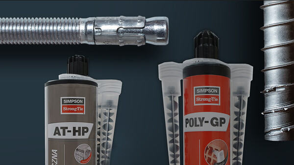
POLY-GP

Resina para diversos materiais

Ancoragem química para cargas médias em alvenaria de blocos maciços e ocos.

Marcação CE
ATE
Utilizable en ambiente húmedo
Interior
Exterior
Dist. bord et entraxe faible

Detalhes do produto

Imagens

Características

Matéria

  • Resina poliéster sem estireno,
  • Haste roscada LMAS : aço eletrogalvanizado e inox A4-7.

Vantagens

  • Fixação rápida: ganho de tempo para o utilizador,
  • Possível de utilizar no interior,
  • Muito bom comportamento ao longo do tempo.

Aplicação

Suporte

  • Alvenaria de blocos maciços e ocos.

Áreas de utilização

  • Estores, gonzos de persianas,
  • Climatizadores,
  • Antenas,
  • Aquecedor de água.

Dados técnicos

Références

Referência Product information
Grey color Beige color Content [ml] Weigth [kg] Packaging qty [pcs]
POLYGP300G-FRx-3000.58612
POLYGP300B-FR-x3000.58612
POLYGP420B-FR-x4200.84212

Design resistance – Tension – NRd [kN] – Carbon steel 5.8

Referência Design resistance – NRd – Carbon steel 5.8 [kN]
Non-cracked concrete
hef = 8d hef = 12d
C20/25 C30/37 C40/50 C50/60 C20/25 C30/37 C40/50 C50/60
POLY-GP + LMAS M84.655.35.56.97.47.98.2
POLY-GP + LMAS M121010.911.61215.116.317.317.9
POLY-GP + LMAS M1614.315.416.41721.423.224.725.5

Concrete :
1. The design loads have been calculated using the partial safety factors for resistances stated in ETA-approval(s). The loading figures are valid for unreinforced concrete and reinforced concrete with a rebar spacing s ≥ 15 cm (any diameter) or with a rebar spacing s ≥ 10 cm, if the rebar diameter is 10mm or smaller.
2. The figures for shear are based on a single anchor without influence of concrete edges. For anchorages close to edges (c ≤ max [10 hef; 60d]) the concrete edge failure shall be checked per ETAG 001, Annex C, design method A.
3. Concrete is considered non-cracked when the tensile stress within the concrete is\sigmaL +\sigmaR ≤ 0. In the absence of detailed verification\sigmaR = 3 N/mm² can be assumed (\sigmaL equals the tensile stress within the concrete induced by external loads, anchors loads included).


Design resistance – Tension – NRd [kN] – Stainless steel A4-70

Referência Design resistance – NRd – Stainless steel A4-70 [kN]
Non-cracked concrete
hef = 8d hef = 12d
C20/25 C30/37 C40/50 C50/60 C20/25 C30/37 C40/50 C50/60
POLY-GP + LMAS M84.655.35.56.97.47.98.2
POLY-GP + LMAS M121010.911.61215.116.317.317.9
POLY-GP + LMAS M1614.315.416.41721.423.224.725.5

Concrete :
1. The design loads have been calculated using the partial safety factors for resistances stated in ETA-approval(s). The loading figures are valid for unreinforced concrete and reinforced concrete with a rebar spacing s ≥ 15 cm (any diameter) or with a rebar spacing s ≥ 10 cm, if the rebar diameter is 10mm or smaller.
2. The figures for shear are based on a single anchor without influence of concrete edges. For anchorages close to edges (c ≤ max [10 hef; 60d]) the concrete edge failure shall be checked per ETAG 001, Annex C, design method A.
3. Concrete is considered non-cracked when the tensile stress within the concrete is\sigmaL +\sigmaR ≤ 0. In the absence of detailed verification\sigmaR = 3 N/mm² can be assumed (\sigmaL equals the tensile stress within the concrete induced by external loads, anchors loads included).


Design resistance – Shear – VRd [kN] – Carbon steel 5.8

Referência Design resistance – VRd – Carbon steel 5.8 [kN]
Non-cracked concrete
hef = 8d hef = 12d
C20/25 C30/37 C40/50 C50/60 C20/25 C30/37 C40/50 C50/60
POLY-GP + LMAS M87.27.27.27.27.27.27.27.2
POLY-GP + LMAS M1216.816.816.816.816.816.816.816.8
POLY-GP + LMAS M1631.231.231.231.231.231.231.231.2

Concrete :
1. The design loads have been calculated using the partial safety factors for resistances stated in ETA-approval(s). The loading figures are valid for unreinforced concrete and reinforced concrete with a rebar spacing s ≥ 15 cm (any diameter) or with a rebar spacing s ≥ 10 cm, if the rebar diameter is 10mm or smaller.
2. The figures for shear are based on a single anchor without influence of concrete edges. For anchorages close to edges (c ≤ max [10 hef; 60d]) the concrete edge failure shall be checked per ETAG 001, Annex C, design method A.
3. Concrete is considered non-cracked when the tensile stress within the concrete is\sigmaL +\sigmaR ≤ 0. In the absence of detailed verification\sigmaR = 3 N/mm² can be assumed (\sigmaL equals the tensile stress within the concrete induced by external loads, anchors loads included).


Design resistance – Shear – VRd [kN] – Stainless steel A4-70

Referência Design resistance – VRd – Stainless steel A4-70 [kN]
Non-cracked concrete
hef = 8d hef = 12d
C20/25 C30/37 C40/50 C50/60 C20/25 C30/37 C40/50 C50/60
POLY-GP + LMAS M88.38.38.38.38.38.38.38.3
POLY-GP + LMAS M1219.219.219.219.219.219.219.219.2
POLY-GP + LMAS M1634.334.334.334.335.335.335.335.3

Concrete :
1. The design loads have been calculated using the partial safety factors for resistances stated in ETA-approval(s). The loading figures are valid for unreinforced concrete and reinforced concrete with a rebar spacing s ≥ 15 cm (any diameter) or with a rebar spacing s ≥ 10 cm, if the rebar diameter is 10mm or smaller.
2. The figures for shear are based on a single anchor without influence of concrete edges. For anchorages close to edges (c ≤ max [10 hef; 60d]) the concrete edge failure shall be checked per ETAG 001, Annex C, design method A.
3. Concrete is considered non-cracked when the tensile stress within the concrete is\sigmaL +\sigmaR ≤ 0. In the absence of detailed verification\sigmaR = 3 N/mm² can be assumed (\sigmaL equals the tensile stress within the concrete induced by external loads, anchors loads included).


Design resistance – Bending moment – MRd [Nm]

Referência Design resistance – Bending moment – MRd [Nm]
Carbon steel 5.8 Stainless steel A4-70
POLY-GP + LMAS M815.216.7
POLY-GP + LMAS M1252.859
POLY-GP + LMAS M16133.6149.4

Concrete :
1. The design loads have been calculated using the partial safety factors for resistances stated in ETA-approval(s). The loading figures are valid for unreinforced concrete and reinforced concrete with a rebar spacing s ≥ 15 cm (any diameter) or with a rebar spacing s ≥ 10 cm, if the rebar diameter is 10mm or smaller.
2. The figures for shear are based on a single anchor without influence of concrete edges. For anchorages close to edges (c ≤ max [10 hef; 60d]) the concrete edge failure shall be checked per ETAG 001, Annex C, design method A.
3. Concrete is considered non-cracked when the tensile stress within the concrete is\sigmaL +\sigmaR ≤ 0. In the absence of detailed verification\sigmaR = 3 N/mm² can be assumed (\sigmaL equals the tensile stress within the concrete induced by external loads, anchors loads included).


Design resistance – hef = 80 mm (≤ M8) or 85 mm (≥ M10) – Carbon steel ≥ 4.6 / Stainless steel ≥ A2-70

Referência Design resistance – Carbon steel ≥ 4.6 / stainless steel ≥ A2-70
hef = 80 mm (≤ M8) or 85 mm ( ≥ M10)
Tension - NRd [kN] Shear - VRd [kN]
Solid Clay Masonry Hollow Masonry Solid Clay Masonry Hollow Masonry
POLY-GP + LMAS M61.60.82.40.8
POLY-GP + LMAS M81.60.82.40.8
POLY-GP + LMAS M121.60.82.80.8

Masonry :


 Compressive strength fb [N/mm²]Bulk density ρ [kg/m3]
Solid clay masonry≥ 18≥ 1600
Hollow masonry≥ 6≥ 900


1. The design resistances have been calculated using the partial safety factors for resistances stated in ETA-approval(s).
2. The recommended loads have been calculated using the partial safety factors for resistances stated in ETA-approval(s) and with a partial safety factor for actions of γF=1.4.
3. For combined tension and shear loads or anchor groups and/or in case of edge influence, a calculation acc. TR 054, design method A shall be performed. For details see ETA - assessment(s)
4. Temperature range: -40°C/+40°C (Tmlp = +24°C)
5. Coefficiant factor β for in situ tests acc. ETAG 029 see ETA-19/0642; Annex C2
6. Displacements under service load see ETA-19/0642; Annex C2 & C3

Design resistance – Bending moment – MRd [Nm]

Referência Design resistance – Bending moment – MRd [Nm]
Carbon steel 5.8 Carbon steel 8.8 Stainless steel ≥ A2-70
POLY-GP + LMAS M66.49.67.1
POLY-GP + LMAS M815.22416.7
POLY-GP + LMAS M1252.88459

Masonry :


 Compressive strength fb [N/mm²]Bulk density [kg/m3]
Solid clay masonry≥ 18≥ 1600
Hollow masonry≥ 6≥ 900


1. The design resistances have been calculated using the partial safety factors for resistances stated in ETA-approval(s).
2. The recommended loads have been calculated using the partial safety factors for resistances stated in ETA-approval(s) and with a partial safety factor for actions of γF=1.4.
3. For combined tension and shear loads or anchor groups and/or in case of edge influence, a calculation acc. TR 054, design method A shall be performed. For details see ETA - assessment(s)
4. Temperature range: -40°C/+40°C (Tmlp = +24°C)
5. Coefficiant factor β for in situ tests acc. ETAG 029 see ETA-19/0642; Annex C2
6. Displacements under service load see ETA-19/0642; Annex C2 & C3


Instalação

Instalação

Temps de pose

Temperatura [C°]

-5

0

5

10

1520

30

Tempo de manipulação

25min

15min

12min8min

7min

4min2min

Tempo até à colocação de carga

4h3h2h301h1555min30min20min

Installation parameters – Concrete

Referência Installation parameters - Concrete
Ø drilling [d0] [mm] Max. fixture hole Ø [df] [mm] Drilling depth (8d) [h0=hef=8d] [mm] Drilling depth (12d) [h0=hef=12d] [mm] Wrench size [SW] Installation torque [Tinst] [Nm]
POLY-GP + LMAS M81096496138
POLY-GP + LMAS M121414961441915
POLY-GP + LMAS M1618181281922425

Spacing, edge distances and member thickness – Concrete

Referência Spacing, edge distance and member thickness - Concrete
Effective embedment depth (8d) [hef,8d] [mm] Characteristic spacing for hef,8d [Scr,N] [mm] Characteristic edge distance for hef,8d [ccr,N] [mm] Min. member thickness for hef,8d [hmin] [mm] Effective embedment depth (12d) [hef,12d] [mm] Characteristic spacing for hef,12d [Scr,N] [mm] Characteristic edge distance for hef,12d [ccr,N] [mm] Min. member thickness for hef,12d [hmin] [mm] Min. spacing [Smin] [mm] Min. edge distance [Cmin] [mm]
8d 12d 8d 12d
POLY-GP + LMAS M864192961009628814412632483248
POLY-GP + LMAS M129628814412614443221617448724872
POLY-GP + LMAS M1612838419215819257628822264966496

Installation parameters – Masonry – Solid clay masonry

Referência Installation parameters - Solid clay masonry
Ø drilling [d0] [mm] Max. fixture hole Ø [df] [mm] Drilling depth [h1] [mm] Installation torque [Tinst] [Nm]
POLY-GP + LMAS M687852
POLY-GP + LMAS M8109852
POLY-GP + LMAS M121414902

Installation parameters – Masonry – Hollow masonry

Referência Installation parameters - Hollow masonry
Ø drilling [d0] [mm] Max. fixture hole Ø [df] [mm] Drilling depth [h1] [mm] Installation torque [Tinst] [Nm]
POLY-GP + LMAS M6127851.5
POLY-GP + LMAS M8129851.5
POLY-GP + LMAS M121614901.5

Spacing, edge distances and member thickness – Masonry – Solid clay masonry

Referência Spacing, edge distance and member thickness - Solid clay masonry
Min. spacing [Smin] [mm] Min. edge distance [Cmin] [mm]
scr,N = smin scr,N ∥ = smin ∥  scr,N T = smin T ccr,N = cmin
POLY-GP + LMAS M6240--120
POLY-GP + LMAS M8240--120
POLY-GP + LMAS M12255--127.5

Spacing, edge distances and member thickness – Masonry – Hollow masonry

Referência Spacing, edge distance and member thickness - Hollow masonry
Min. spacing [Smin] [mm] Min. edge distance [Cmin] [mm]
scr,N = smin scr,N ∥ = smin ∥  scr,NT = sminT ccr,N = cmin
POLY-GP + LMAS M6-250120100
POLY-GP + LMAS M8-250120100
POLY-GP + LMAS M12-250120100

Certification

Declarações de desempenho (DoP)

Homologações técnicas europeia (ETA)

Ficha de segurança (FDS)

Comprar online

No items available.

Contact

Simpson Strong-Tie França

Simpson Strong-Tie

ZAC des 4 Chemins
85400 Sainte-Gemme-la-Plaine
França