
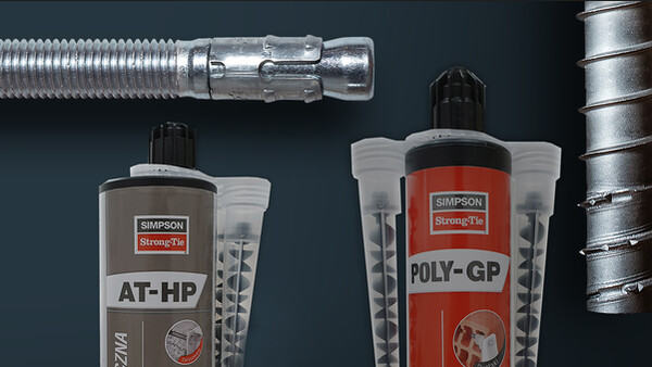

POLY-GPG
Resina para diversos materiais
Esta solução de fixação química abrange 100% das aplicações correntes (fixações de estores, persianas, caldeiras, ...). Pode ser utilizada sem riscos no interior (COV A+) e pode ser eliminada juntamente com os resíduos normais.
Marcação CE
ATE
Utilizable en ambiente húmedo
Interior
Exterior
Dist. bord et entraxe faible

Detalhes do produto
Imagens


Características
Matéria
- Resina de metacrilato,
- Haste roscada LMAS : aço eletrogalvanizado e inox A4-70.
Vantagens
- Embalagem em cartucho : utilização simples e rápida,
- Sem ingredientes perigosos, sem estireno e sem cheiro,
- Sem símbolos de perigo e frases sobre riscos,
- Armazenamento na zona para produtos “não inflamáveis”,
- O cartucho (utilizado ou não) pode ser eliminado nos contentores de resíduos não perigosos.
Aplicação
Suporte
- Tijolo,
- Perpianho,
- Betão celular.
Áreas de utilização
- Estores, gonzos de persianas/portais, antenas,
- Climatizadores, aquecedor de água, sanitários, radiadores,
- Corrimões/vedações.
Dados técnicos
Références
| Referência | Product information | ||||
|---|---|---|---|---|---|
| Grey color | Beige color | Content [ml] | Weigth [kg] | Packaging qty [pcs] | |
| POLYGPG300G-FR | x | - | 300 | 0.579 | 12 |
| POLYGPG300B-FR | - | x | 300 | 0.579 | 12 |
Design resistance – Tension – NRd [kN] – Carbon steel 5.8
| Referência | Design resistance – NRd – Carbon steel 5.8 [kN] | |||||||
|---|---|---|---|---|---|---|---|---|
| Non-cracked concrete | ||||||||
| hef = 8d | hef = 12d | |||||||
| C20/25 | C30/37 | C40/50 | C50/60 | C20/25 | C30/37 | C40/50 | C50/60 | |
| POLY-GPG + LMAS M8 | 6.3 | 6.3 | 6.3 | 6.3 | 9.4 | 9.4 | 9.4 | 9.4 |
| POLY-GPG + LMAS M10 | 9.8 | 9.8 | 9.8 | 9.8 | 14.7 | 14.7 | 14.7 | 14.7 |
| POLY-GPG + LMAS M12 | 13.1 | 13.1 | 13.1 | 13.1 | 19.6 | 19.6 | 19.6 | 19.6 |
| POLY-GPG + LMAS M16 | 19.9 | 19.9 | 19.9 | 19.9 | 29.9 | 29.9 | 29.9 | 29.9 |
| POLY-GPG + LMAS M20 | 28.7 | 28.7 | 28.7 | 28.7 | 43.1 | 43.1 | 43.1 | 43.1 |
| POLY-GPG + LMAS M24 | 37.9 | 37.9 | 37.9 | 37.9 | 56.8 | 56.8 | 56.8 | 56.8 |
Concrete :
1. The design loads have been calculated using the partial safety factors for resistances stated in ETA-approval(s). The loading figures are valid for unreinforced concrete and reinforced concrete with a rebar spacing s ≥ 15 cm (any diameter) or with a rebar spacing s ≥ 10 cm, if the rebar diameter is 10mm or smaller.
2. The figures for shear are based on a single anchor without influence of concrete edges. For anchorages close to edges (c ≤ max [10 hef; 60d]) the concrete edge failure shall be checked per ETAG 001, Annex C, design method A.
3. Concrete is considered non-cracked when the tensile stress within the concrete is\sigmaL +\sigmaR ≤ 0. In the absence of detailed verification\sigmaR = 3 N/mm² can be assumed (\sigmaL equals the tensile stress within the concrete induced by external loads, anchors loads included).
Design resistance – Tension – NRd [kN] – Stainless steel A4-70
| Referência | Design resistance – NRd – Stainless steel A4-70 [kN] | |||||||
|---|---|---|---|---|---|---|---|---|
| Non-cracked concrete | ||||||||
| hef = 8d | hef = 12d | |||||||
| C20/25 | C30/37 | C40/50 | C50/60 | C20/25 | C30/37 | C40/50 | C50/60 | |
| POLY-GPG + LMAS M8 | 6.3 | 6.3 | 6.3 | 6.3 | 9.4 | 9.4 | 9.4 | 9.4 |
| POLY-GPG + LMAS M10 | 9.8 | 9.8 | 9.8 | 9.8 | 14.7 | 14.7 | 14.7 | 14.7 |
| POLY-GPG + LMAS M12 | 13.1 | 13.1 | 13.1 | 13.1 | 19.6 | 19.6 | 19.6 | 19.6 |
| POLY-GPG + LMAS M16 | 19.9 | 19.9 | 19.9 | 19.9 | 29.9 | 29.9 | 29.9 | 29.9 |
| POLY-GPG + LMAS M20 | 28.7 | 28.7 | 28.7 | 28.7 | 43.1 | 43.1 | 43.1 | 43.1 |
| POLY-GPG + LMAS M24 | 37.9 | 37.9 | 37.9 | 37.9 | 56.8 | 56.8 | 56.8 | 56.8 |
Concrete :
1. The design loads have been calculated using the partial safety factors for resistances stated in ETA-approval(s). The loading figures are valid for unreinforced concrete and reinforced concrete with a rebar spacing s ≥ 15 cm (any diameter) or with a rebar spacing s ≥ 10 cm, if the rebar diameter is 10mm or smaller.
2. The figures for shear are based on a single anchor without influence of concrete edges. For anchorages close to edges (c ≤ max [10 hef; 60d]) the concrete edge failure shall be checked per ETAG 001, Annex C, design method A.
3. Concrete is considered non-cracked when the tensile stress within the concrete is\sigmaL +\sigmaR ≤ 0. In the absence of detailed verification\sigmaR = 3 N/mm² can be assumed (\sigmaL equals the tensile stress within the concrete induced by external loads, anchors loads included).
Design resistance – Shear – VRd [kN] – Carbon steel 5.8
| Referência | Design resistance – VRd – Carbon steel 5.8 [kN] | |||||||
|---|---|---|---|---|---|---|---|---|
| Non-cracked concrete | ||||||||
| hef = 8d | hef = 12d | |||||||
| C20/25 | C30/37 | C40/50 | C50/60 | C20/25 | C30/37 | C40/50 | C50/60 | |
| POLY-GPG + LMAS M8 | 7.2 | 7.2 | 7.2 | 7.2 | 7.2 | 7.2 | 7.2 | 7.2 |
| POLY-GPG + LMAS M10 | 12 | 12 | 12 | 12 | 12 | 12 | 12 | 12 |
| POLY-GPG + LMAS M12 | 16.8 | 16.8 | 16.8 | 16.8 | 16.8 | 16.8 | 16.8 | 16.8 |
| POLY-GPG + LMAS M16 | 31.2 | 31.2 | 31.2 | 31.2 | 31.2 | 31.2 | 31.2 | 31.2 |
| POLY-GPG + LMAS M20 | 48.8 | 48.8 | 48.8 | 48.8 | 48.8 | 48.8 | 48.8 | 48.8 |
| POLY-GPG + LMAS M24 | 70.4 | 70.4 | 70.4 | 70.4 | 70.4 | 70.4 | 70.4 | 70.4 |
Concrete :
1. The design loads have been calculated using the partial safety factors for resistances stated in ETA-approval(s). The loading figures are valid for unreinforced concrete and reinforced concrete with a rebar spacing s ≥ 15 cm (any diameter) or with a rebar spacing s ≥ 10 cm, if the rebar diameter is 10mm or smaller.
2. The figures for shear are based on a single anchor without influence of concrete edges. For anchorages close to edges (c ≤ max [10 hef; 60d]) the concrete edge failure shall be checked per ETAG 001, Annex C, design method A.
3. Concrete is considered non-cracked when the tensile stress within the concrete is\sigmaL +\sigmaR ≤ 0. In the absence of detailed verification\sigmaR = 3 N/mm² can be assumed (\sigmaL equals the tensile stress within the concrete induced by external loads, anchors loads included).
Design resistance – Shear – VRd [kN] – Stainless steel A4-70
| Referência | Design resistance – VRd – Stainless steel A4-70 [kN] | |||||||
|---|---|---|---|---|---|---|---|---|
| Non-cracked concrete | ||||||||
| hef = 8d | hef = 12d | |||||||
| C20/25 | C30/37 | C40/50 | C50/60 | C20/25 | C30/37 | C40/50 | C50/60 | |
| POLY-GPG + LMAS M8 | 8.3 | 8.3 | 8.3 | 8.3 | 8.3 | 8.3 | 8.3 | 8.3 |
| POLY-GPG + LMAS M10 | 12.8 | 12.8 | 12.8 | 12.8 | 12.8 | 12.8 | 12.8 | 12.8 |
| POLY-GPG + LMAS M12 | 19.2 | 19.2 | 19.2 | 19.2 | 19.2 | 19.2 | 19.2 | 19.2 |
| POLY-GPG + LMAS M16 | 35.3 | 35.3 | 35.3 | 35.3 | 35.3 | 35.3 | 35.3 | 35.3 |
| POLY-GPG + LMAS M20 | 55.1 | 55.1 | 55.1 | 55.1 | 55.1 | 55.1 | 55.1 | 55.1 |
| POLY-GPG + LMAS M24 | 79.5 | 79.5 | 79.5 | 79.5 | 79.5 | 79.5 | 79.5 | 79.5 |
Concrete :
1. The design loads have been calculated using the partial safety factors for resistances stated in ETA-approval(s). The loading figures are valid for unreinforced concrete and reinforced concrete with a rebar spacing s ≥ 15 cm (any diameter) or with a rebar spacing s ≥ 10 cm, if the rebar diameter is 10mm or smaller.
2. The figures for shear are based on a single anchor without influence of concrete edges. For anchorages close to edges (c ≤ max [10 hef; 60d]) the concrete edge failure shall be checked per ETAG 001, Annex C, design method A.
3. Concrete is considered non-cracked when the tensile stress within the concrete is\sigmaL +\sigmaR ≤ 0. In the absence of detailed verification\sigmaR = 3 N/mm² can be assumed (\sigmaL equals the tensile stress within the concrete induced by external loads, anchors loads included).
Design resistance – Bending moment – MRd [Nm] – Concrete
| Referência | Design resistance – Bending moment – MRd - Concrete [Nm] | |
|---|---|---|
| Carbon steel 5.8 | Stainless steel A4-70 | |
| POLY-GPG + LMAS M8 | 15.2 | 16.7 |
| POLY-GPG + LMAS M10 | 29.6 | 33.3 |
| POLY-GPG + LMAS M12 | 52 | 60.9 |
| POLY-GPG + LMAS M16 | 132.8 | 148.7 |
| POLY-GPG + LMAS M20 | 259.2 | 291 |
| POLY-GPG + LMAS M24 | 448 | 502.6 |
Concrete :
1. The design loads have been calculated using the partial safety factors for resistances stated in ETA-approval(s). The loading figures are valid for unreinforced concrete and reinforced concrete with a rebar spacing s ≥ 15 cm (any diameter) or with a rebar spacing s ≥ 10 cm, if the rebar diameter is 10mm or smaller.
2. The figures for shear are based on a single anchor without influence of concrete edges. For anchorages close to edges (c ≤ max [10 hef; 60d]) the concrete edge failure shall be checked per ETAG 001, Annex C, design method A.
3. Concrete is considered non-cracked when the tensile stress within the concrete is\sigmaL +\sigmaR ≤ 0. In the absence of detailed verification\sigmaR = 3 N/mm² can be assumed (\sigmaL equals the tensile stress within the concrete induced by external loads, anchors loads included).
Design resistance – hef = 80 mm (≤ M8) or 85 mm (≥ M10) – Carbon steel ≥ 4.6 / Stainless steel ≥ A2-70
| Referência | Design resistance – Carbon steel ≥ 4.6 / stainless steel ≥ A2-70 | |||
|---|---|---|---|---|
| hef = 80 mm (≤ M8) or 85 mm ( ≥ M10) | ||||
| Tension - NRd [kN] | Shear - VRd [kN] | |||
| Solid Clay Masonry | Hollow Masonry | Solid Clay Masonry | Hollow Masonry | |
| POLY-GPG + LMAS M8 | 1.6 | 0.3 | 0.8 | 0.6 |
| POLY-GPG + LMAS M10 | 2 | 0.6 | 2.4 | 0.6 |
| POLY-GPG + LMAS M12 | 2 | 0.6 | 2.4 | 0.6 |
| POLY-GPG + LMAS M16 | - | - | - | - |
| POLY-GPG + LMAS M20 | - | - | - | - |
| POLY-GPG + LMAS M24 | - | - | - | - |
Masonry :
| Compressive strength fb [N/mm²] | Bulk density ρ [kg/m3] | |
| Solid clay masonry | ≥ 18 | ≥ 1600 |
| Hollow masonry | ≥ 6 | ≥ 900 |
1. The design resistances have been calculated using the partial safety factors for resistances stated in ETA-approval(s).
2. The recommended loads have been calculated using the partial safety factors for resistances stated in ETA-approval(s) and with a partial safety factor for actions of γF=1.4.
3. For combined tension and shear loads or anchor groups and/or in case of edge influence, a calculation acc. TR 054, design method A shall be performed. For details see ETA - assessment(s)
4. Temperature range: -40°C/+40°C (Tmlp = +24°C)
5. Coefficiant factor β for in situ tests acc. ETAG 029 see ETA-19/XXXX; Annex C2
6. Displacements under service load see ETA-19/0420; Annex C2 & C3
Design resistance – Bending moment – MRd [Nm] – Masonry
| Referência | Design resistance – Bending moment – MRd - Masonry [Nm] | ||
|---|---|---|---|
| Carbon steel 5.8 | Carbon steel 8.8 | Stainless steel ≥ A2-70 | |
| POLYGPG300G-FR | - | - | - |
| POLYGPG300B-FR | - | - | - |
| POLY-GPG + LMAS M6 | 6.4 | 9.6 | 7.1 |
| POLY-GPG + LMAS M8 | 15.2 | 24 | 16.7 |
| POLY-GPG + LMAS M10 | 29.6 | 48 | 33.3 |
| POLY-GPG + LMAS M12 | 52.8 | 84 | 59 |
| POLY-GPG + LMAS M16 | - | - | - |
| POLY-GPG + LMAS M20 | - | - | - |
| POLY-GPG + LMAS M24 | - | - | - |
| POLY-GPG + Ø8 | - | - | - |
| POLY-GPG + Ø10 | - | - | - |
| POLY-GPG + Ø12 | - | - | - |
| POLY-GPG + Ø16 | - | - | - |
| POLY-GPG + Ø20 | - | - | - |
| POLY-GPG + Ø25 | - | - | - |
| POLYGPG300BG-SE | - | - | - |
Masonry :
| Compressive strength fb [N/mm²] | Bulk density ρ [kg/m3] | |
| Solid clay masonry | ≥ 18 | ≥ 1600 |
| Hollow masonry | ≥ 6 | ≥ 900 |
1. The design resistances have been calculated using the partial safety factors for resistances stated in ETA-approval(s).
2. The recommended loads have been calculated using the partial safety factors for resistances stated in ETA-approval(s) and with a partial safety factor for actions of γF=1.4.
3. For combined tension and shear loads or anchor groups and/or in case of edge influence, a calculation acc. TR 054, design method A shall be performed. For details see ETA - assessment(s)
4. Temperature range: -40°C/+40°C (Tmlp = +24°C)
5. Coefficiant factor β for in situ tests acc. ETAG 029 see ETA-19/XXXX; Annex C2
6. Displacements under service load see ETA-19/0420; Annex C2 & C3
Design resistance – Tension – NRd [kN] – Rebar
| Referência | Design resistance – NRd – Rebar [kN] | |||||||
|---|---|---|---|---|---|---|---|---|
| Non-cracked concrete | ||||||||
| hef = 8d | hef = 12d | |||||||
| C20/25 | C30/37 | C40/50 | C50/60 | C20/25 | C30/37 | C40/50 | C50/60 | |
| POLY-GPG + Ø8 | 4.9 | 4.9 | 4.9 | 4.9 | 7.4 | 7.4 | 7.4 | 7.4 |
| POLY-GPG + Ø10 | 7.7 | 7.7 | 8.4 | 8.4 | 11.5 | 11.5 | 12.7 | 12.7 |
| POLY-GPG + Ø12 | 11.1 | 12.2 | 12.2 | 13.3 | 16.6 | 18.2 | 18.2 | 19.9 |
| POLY-GPG + Ø16 | 15.3 | 16.8 | 16.8 | 18.4 | 23 | 25.3 | 25.3 | 27.6 |
| POLY-GPG + Ø20 | 23.9 | 26.3 | 26.3 | 28.7 | 35.9 | 39.5 | 39.5 | 43.1 |
| POLY-GPG + Ø25 | 37.4 | 41.1 | 44.9 | 48.6 | 53.8 | 59.2 | 64.6 | 70 |
Design resistance – Shear – VRd [kN] – Rebar
| Referência | Design resistance – VRd – Rebar [kN] | |||||||
|---|---|---|---|---|---|---|---|---|
| Non-cracked concrete | ||||||||
| hef = 8d | hef = 12d | |||||||
| C20/25 | C30/37 | C40/50 | C50/60 | C20/25 | C30/37 | C40/50 | C50/60 | |
| POLY-GPG + Ø8 | 9 | 9 | 9 | 9 | 9 | 9 | 9 | 9 |
| POLY-GPG + Ø10 | 14.2 | 14.2 | 14.2 | 14.2 | 14.2 | 14.2 | 14.2 | 14.2 |
| POLY-GPG + Ø12 | 20.3 | 20.3 | 20.3 | 20.3 | 20.3 | 20.3 | 20.3 | 20.3 |
| POLY-GPG + Ø16 | 36.2 | 36.2 | 36.2 | 36.2 | 36.2 | 36.2 | 36.2 | 36.2 |
| POLY-GPG + Ø20 | 56.5 | 56.5 | 56.5 | 56.5 | 56.5 | 56.5 | 56.5 | 56.5 |
| POLY-GPG + Ø25 | 88.4 | 88.4 | 88.4 | 88.4 | 88.4 | 88.4 | 88.4 | 88.4 |
Design resistance – Bending moment – MRd [Nm] – Rebar
| Referência | Design resistance – Bending moment – MRd – Rebar [Nm] |
|---|---|
| POLY-GPG + Ø8 | 21.6 |
| POLY-GPG + Ø10 | 42.3 |
| POLY-GPG + Ø12 | 73.5 |
| POLY-GPG + Ø16 | 173.7 |
| POLY-GPG + Ø20 | 339.1 |
| POLY-GPG + Ø25 | 662.7 |
Instalação
Instalação
Temps de pose
Temperatura [C°] | -5°C | 0°C | 5°C | 10°C | 20°C | 30°C |
Tempo de manipulação | 2h15 | 1h15 | 25min | 12min | 6min | 2min |
Tempo até à colocação de carga | 4h00 | 2h00 | 1h30 | 40min | 20min | 15min |

Perfurar.

Escovar.

Inserir uma peneira.

Encher do fundo para o exterior, recunado uma gradaçao na boquilha de injeçao a cada bombada.

Inserir a haste fazendo rodar lentamente.

Fixar assim que se atingir o tempo de colocaçao em carga.

Perfurar.

Limpar com uma escova e sopro, conforme especificado na cartucho.

Encher 1/2 a 2/3 do buraco, do fundo para o exterior, recuando uma gradaçao, na boquilha de injeçao a cada bombada.

Inserir a haste fazendo rodar lentamente da esquerda para a direita.

Fixar assim que se atingir o tempo de colocaçao em carga.
Installation parameters – Concrete
| Referência | Installation parameters - Concrete | |||||
|---|---|---|---|---|---|---|
| Ø drilling [d0] [mm] | Max. fixture hole Ø [df] [mm] | Drilling depth (8d) [h0=hef=8d] [mm] | Drilling depth (12d) [h0=hef=12d] [mm] | Wrench size [SW] | Installation torque [Tinst] [Nm] | |
| POLY-GPG + LMAS M8 | 10 | 9 | 64 | 96 | 13 | 10 |
| POLY-GPG + LMAS M10 | 12 | 12 | 80 | 120 | 17 | 12 |
| POLY-GPG + LMAS M12 | 14 | 14 | 96 | 144 | 19 | 20 |
| POLY-GPG + LMAS M16 | 18 | 18 | 128 | 196 | 24 | 40 |
| POLY-GPG + LMAS M20 | 24 | 22 | 160 | 240 | 30 | 70 |
| POLY-GPG + LMAS M24 | 28 | 26 | 192 | 288 | 36 | 90 |
Spacing, edge distances and member thickness – Concrete
| Referência | Spacing, edge distance and member thickness - Concrete | |||||||||
|---|---|---|---|---|---|---|---|---|---|---|
| Effective embedment depth (8d) [hef,8d] [mm] | Characteristic spacing for hef,8d [Scr,N] [mm] | Characteristic edge distance for hef,8d [ccr,N] [mm] | Min. member thickness for hef,8d [hmin] [mm] | Effective embedment depth (12d) [hef,12d] [mm] | Characteristic spacing for hef,12d [Scr,N] [mm] | Characteristic edge distance for hef,12d [ccr,N] [mm] | Min. member thickness for hef,12d [hmin] [mm] | Min. spacing [Smin] [mm] | Min. edge distance [Cmin] [mm] | |
| POLY-GPG + LMAS M8 | 64 | 192 | 96 | 100 | 96 | 288 | 144 | 126 | 40 | 40 |
| POLY-GPG + LMAS M10 | 80 | 240 | 120 | 110 | 120 | 360 | 180 | 150 | 50 | 50 |
| POLY-GPG + LMAS M12 | 96 | 288 | 144 | 126 | 144 | 432 | 216 | 174 | 60 | 60 |
| POLY-GPG + LMAS M16 | 128 | 384 | 192 | 158 | 196 | 588 | 294 | 226 | 80 | 80 |
| POLY-GPG + LMAS M20 | 160 | 480 | 240 | 190 | 240 | 720 | 360 | 270 | 100 | 100 |
| POLY-GPG + LMAS M24 | 192 | 576 | 288 | 222 | 288 | 864 | 432 | 318 | 120 | 120 |
Installation parameters – Masonry – Solid clay masonry
| Referência | Installation parameters - Solid clay masonry | ||||
|---|---|---|---|---|---|
| Ø drilling [d0] [mm] | Max. fixture hole Ø [df] [mm] | Drilling depth [h1] [mm] | Embedment depth [hef] [mm] | Installation torque [Tinst] [Nm] | |
| POLY-GPG + LMAS M6 | 8 | 7 | 85 | 80 | 1 |
| POLY-GPG + LMAS M8 | 10 | 9 | 85 | 80 | 1 |
| POLY-GPG + LMAS M10 | 12 | 12 | 90 | 85 | 1 |
| POLY-GPG + LMAS M12 | 14 | 14 | 90 | 85 | 1 |
Installation parameters – Masonry – Hollow masonry
| Referência | Installation parameters - Hollow masonry | ||||
|---|---|---|---|---|---|
| Ø drilling [d0] [mm] | Max. fixture hole Ø [df] [mm] | Drilling depth [h1] [mm] | Embedment depth [hef] [mm] | Installation torque [Tinst] [Nm] | |
| POLY-GPG + LMAS M6 | 12 | 7 | 85 | 80 | 2 |
| POLY-GPG + LMAS M8 | 12 | 9 | 85 | 80 | 2 |
| POLY-GPG + LMAS M10 | 16 | 12 | 90 | 85 | 2 |
| POLY-GPG + LMAS M12 | 16 | 14 | 90 | 85 | 2 |
Spacing, edge distances and member thickness – Masonry – Solid clay masonry
| Referência | Spacing, edge distance and member thickness - Solid clay masonry | |||
|---|---|---|---|---|
| Min. spacing [Smin] [mm] | Min. edge distance [Cmin] [mm] | |||
| scr,N = smin [mm] | scr,N ∥ = smin ∥ [mm] | scr,NT = sminT [mm] | ccr,N = cmin [mm] | |
| POLY-GPG + LMAS M6 | 240 | - | - | 120 |
| POLY-GPG + LMAS M8 | 240 | - | - | 120 |
| POLY-GPG + LMAS M10 | 255 | - | - | 127.5 |
| POLY-GPG + LMAS M12 | 255 | - | - | 127.5 |
Spacing, edge distances and member thickness – Masonry – Hollow masonry
| Referência | Spacing, edge distance and member thickness - Hollow masonry | |||
|---|---|---|---|---|
| Min. spacing [Smin] [mm] | Min. edge distance [Cmin] [mm] | |||
| scr,N = smin [mm] | scr,N ∥ = smin ∥ [mm] | scr,N T = smin T [mm] | ccr,N = cmin [mm] | |
| POLY-GPG + LMAS M6 | - | 250 | 120 | 100 |
| POLY-GPG + LMAS M8 | - | 250 | 120 | 100 |
| POLY-GPG + LMAS M10 | - | 250 | 120 | 100 |
| POLY-GPG + LMAS M12 | - | 250 | 120 | 100 |
Installation parameters – Rebar
| Referência | Installation parameters – Rebar | ||
|---|---|---|---|
| Ø drilling [d0] [mm] | Drilling depth (8d) [h0=hef=8d] [mm] | Drilling depth (12d) [h0=hef=12d] [mm] | |
| POLY-GPG + Ø8 | 12 | 64 | 96 |
| POLY-GPG + Ø10 | 14 | 80 | 120 |
| POLY-GPG + Ø12 | 16 | 96 | 144 |
| POLY-GPG + Ø16 | 20 | 128 | 192 |
| POLY-GPG + Ø20 | 25 | 160 | 240 |
| POLY-GPG + Ø25 | 32 | 200 | 288 |
Spacing, edge distances and member thickness – Rebar
| Referência | Spacing, edge distance and member thickness – Rebar | |||||||||
|---|---|---|---|---|---|---|---|---|---|---|
| Effective embedment depth (8d) [hef,8d] [mm] | Characteristic spacing for hef,8d [Scr,N] [mm] | Characteristic edge distance for hef,8d [ccr,N] [mm] | Min. member thickness for hef,8d [hmin] [mm] | Effective embedment depth (12d) [hef,12d] [mm] | Characteristic spacing for hef,12d [Scr,N] [mm] | Characteristic edge distance for hef,12d [ccr,N] [mm] | Min. member thickness for hef,12d [hmin] [mm] | Min. spacing [Smin] [mm] | Min. edge distance [Cmin] [mm] | |
| POLY-GPG + Ø8 | 64 | 192 | 96 | 100 | 96 | 288 | 144 | 126 | 40 | 40 |
| POLY-GPG + Ø10 | 80 | 240 | 120 | 110 | 120 | 360 | 180 | 150 | 50 | 50 |
| POLY-GPG + Ø12 | 96 | 288 | 144 | 126 | 144 | 432 | 216 | 174 | 60 | 60 |
| POLY-GPG + Ø16 | 128 | 384 | 192 | 168 | 192 | 576 | 288 | 232 | 80 | 80 |
| POLY-GPG + Ø20 | 160 | 480 | 240 | 210 | 240 | 720 | 360 | 290 | 100 | 100 |
| POLY-GPG + Ø25 | 200 | 600 | 300 | 264 | 288 | 864 | 432 | 352 | 120 | 120 |
Certification
Declarações de desempenho (DoP)
pt-dop-e19-0420-01.pdf
(103.77 KB)
pt-dop-e19-0626-01.pdf
(102.92 KB)
pt-dop-e19-0627-01.pdf
(102.47 KB)
Homologações técnicas europeia (ETA)
eta190420-sst-poly-gpg-masonry.pdf
(1.35 MB)
eta-19-0626.pdf
(1.4 MB)
eta-19-0627.pdf
(1.16 MB)
