
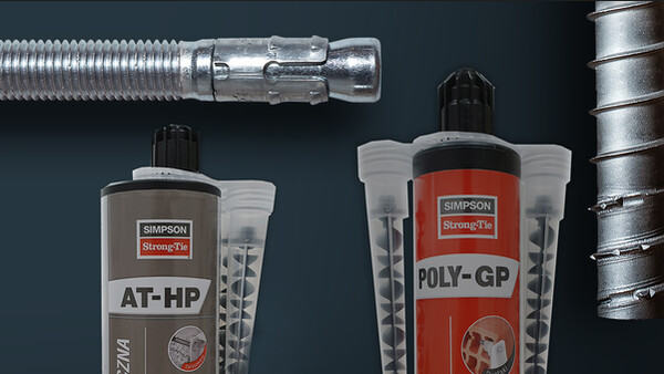

AT-HP
Resina de elevado desempenho multimateriais
A resina de betão para cargas pesadas AT-HP é adequada para fixar betão armado, hastes roscadas em betão fissurado e não fissurado e C20/25 a C50/60.
Marcação CE
ATE
Fogo
Interior
Exterior
Dist. bord et entraxe faible

Detalhes do produto
Imagens


Características
Matéria
- Resina de metacrilato sem estireno,
- Haste roscada : aço eletrogalvanizado e inox A4-70.
Vantagens
- Valor de aderência elevado no betão e em alvenaria,
- Muito bom comportamento em furos húmidos e/ou molhados,
- Resistência ao fogo,
- 2 ATE para as hastes roscadas em betão e alvenaria,
- 1 ATE para a recuperação de betão armado.
Aplicação
Suporte
- Betão, betão celular,
- Tijolo oco e maciço,
- Perpianho oco e maciço.
Áreas de utilização
- Recuperação de betão armado,
- Fixação de hastes em betão,
- Fixação de hastes em alvenaria,
- Balcões,
- Fachadas,
- Bastidores.
Dados técnicos
Références
| Referência | Product information | ||||||
|---|---|---|---|---|---|---|---|
| DB nr. | NOBB nr. | Grey color | Beige color | Content [ml] | Weight [kg] | Packaging qty [pcs] | |
| ATHP300G-FR | - | - | x | - | 300 | 0.575 | 12 |
| ATHP420G-FR | - | - | x | - | 420 | 0.828 | 12 |
| ATHP420BG-PL | - | - | x | - | 420 | 0.828 | 12 |
| ATHP300BG-PL | - | - | x | - | 300 | 0.575 | 12 |
| ATHP300BG-DK | 2099761 | 56432785 | - | - | 300 | 0.575 | 12 |
Design resistance – Tension – NRd [kN] – hef = 8d – Carbon steel 5.8
| Referência | Design resistance – hef = 8d – Carbon steel 5.8 | |||||||
|---|---|---|---|---|---|---|---|---|
| Tension - NRd [kN] | ||||||||
| Cracked concrete | Non-cracked concrete | |||||||
| C20/25 | C30/37 | C40/50 | C50/60 | C20/25 | C30/37 | C40/50 | C50/60 | |
| AT-HP + LMAS M8 | - | - | - | - | 10.7 | 12 | 12 | 12 |
| AT-HP + LMAS M10 | - | - | - | - | 15.9 | 17.8 | 19.3 | 19.3 |
| AT-HP + LMAS M12 | 8.4 | 8.8 | 9 | 9.2 | 21.7 | 24.3 | 26.7 | 28 |
| AT-HP + LMAS M16 | 15 | 15.6 | 16.1 | 16.4 | 34.3 | 38.4 | 42.2 | 44.6 |
| AT-HP + LMAS M20 | - | - | - | - | 50.2 | 56.3 | 61.8 | 65.3 |
| AT-HP + LMAS M24 | - | - | - | - | 67.5 | 75.6 | 83.1 | 87.8 |
Concrete :
1. The design loads have been calculated using the partial safety factors for resistances stated in ETA-approval(s). The loading figures are valid for unreinforced concrete and reinforced concrete with a rebar spacing s ≥ 15 cm (any diameter) or with a rebar spacing s ≥ 10 cm, if the rebar diameter is 10mm or smaller.
2. The figures for shear are based on a single anchor without influence of concrete edges. For anchorages close to edges (c ≤ max [10 hef; 60d]) the concrete edge failure shall be checked per ETAG 001, Annex C, design method A.
3. Concrete is considered non-cracked when the tensile stress within the concrete is\sigmaL +\sigmaR ≤ 0. In the absence of detailed verification\sigmaR = 3 N/mm² can be assumed (\sigmaL equals the tensile stress within the concrete induced by external loads, anchors loads included).
Design resistance – Tension – NRd [kN] – hef = 12d – Carbon steel 5.8
| Referência | Design resistance – hef = 12d – Carbon steel 5.8 | |||||||
|---|---|---|---|---|---|---|---|---|
| Tension - NRd [kN] | ||||||||
| Cracked concrete | Non-cracked concrete | |||||||
| C20/25 | C30/37 | C40/50 | C50/60 | C20/25 | C30/37 | C40/50 | C50/60 | |
| AT-HP + LMAS M8 | - | - | - | - | 12 | 12 | 12 | 12 |
| AT-HP + LMAS M10 | - | - | - | - | 19.3 | 19.3 | 19.3 | 19.3 |
| AT-HP + LMAS M12 | 12.7 | 13.2 | 13.5 | 13.8 | 28 | 28 | 28 | 28 |
| AT-HP + LMAS M16 | 22.5 | 23.4 | 24.1 | 24.5 | 51.4 | 52.7 | 52.7 | 52.7 |
| AT-HP + LMAS M20 | - | - | - | - | 75.4 | 82 | 82 | 82 |
| AT-HP + LMAS M24 | - | - | - | - | 101.3 | 113.4 | 118 | 118 |
Concrete :
1. The design loads have been calculated using the partial safety factors for resistances stated in ETA-approval(s). The loading figures are valid for unreinforced concrete and reinforced concrete with a rebar spacing s ≥ 15 cm (any diameter) or with a rebar spacing s ≥ 10 cm, if the rebar diameter is 10mm or smaller.
2. The figures for shear are based on a single anchor without influence of concrete edges. For anchorages close to edges (c ≤ max [10 hef; 60d]) the concrete edge failure shall be checked per ETAG 001, Annex C, design method A.
3. Concrete is considered non-cracked when the tensile stress within the concrete is\sigmaL +\sigmaR ≤ 0. In the absence of detailed verification\sigmaR = 3 N/mm² can be assumed (\sigmaL equals the tensile stress within the concrete induced by external loads, anchors loads included).
Design resistance – Tension – NRd [kN] – hef = 8d – Stainless steel A4-70
| Referência | Design resistance – hef = 8d – Stainless steel A4-70 | |||||||
|---|---|---|---|---|---|---|---|---|
| Tension - NRd [kN] | ||||||||
| Cracked concrete | Non-cracked concrete | |||||||
| C20/25 | C30/37 | C40/50 | C50/60 | C20/25 | C30/37 | C40/50 | C50/60 | |
| ATHP300BG-PL | - | - | - | - | - | - | - | - |
| AT-HP + LMAS M8 | - | - | - | - | 10.7 | 12 | 13.2 | 13.9 |
| AT-HP + LMAS M10 | - | - | - | - | 15.9 | 17.8 | 19.6 | 20.7 |
| AT-HP + LMAS M12 | 8.4 | 8.8 | 9 | 9.2 | 21.7 | 24.3 | 26.7 | 28.2 |
| AT-HP + LMAS M16 | 15 | 15.6 | 16.1 | 16.4 | 34.3 | 38.4 | 42.2 | 44.6 |
| AT-HP + LMAS M20 | - | - | - | - | 50.2 | 56.3 | 61.8 | 65.3 |
| AT-HP + LMAS M24 | - | - | - | - | 67.5 | 75.6 | 83.1 | 87.8 |
Concrete :
1. The design loads have been calculated using the partial safety factors for resistances stated in ETA-approval(s). The loading figures are valid for unreinforced concrete and reinforced concrete with a rebar spacing s ≥ 15 cm (any diameter) or with a rebar spacing s ≥ 10 cm, if the rebar diameter is 10mm or smaller.
2. The figures for shear are based on a single anchor without influence of concrete edges. For anchorages close to edges (c ≤ max [10 hef; 60d]) the concrete edge failure shall be checked per ETAG 001, Annex C, design method A.
3. Concrete is considered non-cracked when the tensile stress within the concrete is\sigmaL +\sigmaR ≤ 0. In the absence of detailed verification\sigmaR = 3 N/mm² can be assumed (\sigmaL equals the tensile stress within the concrete induced by external loads, anchors loads included).
Design resistance – Tension – NRd [kN] – hef = 12d – Stainless steel A4-70
| Referência | Design resistance – hef = 12d – Stainless steel A4-70 | |||||||
|---|---|---|---|---|---|---|---|---|
| Tension - NRd [kN] | ||||||||
| Cracked concrete | Non-cracked concrete | |||||||
| C20/25 | C30/37 | C40/50 | C50/60 | C20/25 | C30/37 | C40/50 | C50/60 | |
| AT-HP + LMAS M8 | - | - | - | - | 13.9 | 13.9 | 13.9 | 13.9 |
| AT-HP + LMAS M10 | - | - | - | - | 21.9 | 21.9 | 21.9 | 21.9 |
| AT-HP + LMAS M12 | 12.7 | 13.2 | 13.5 | 13.8 | 31.6 | 31.6 | 31.6 | 31.6 |
| AT-HP + LMAS M16 | 22.5 | 23.4 | 24.1 | 24.5 | 51.4 | 57.6 | 58.8 | 58.8 |
| AT-HP + LMAS M20 | - | - | - | - | 75.4 | 84.4 | 92 | 92 |
| AT-HP + LMAS M24 | - | - | - | - | 101.3 | 113.4 | 124.6 | 131.7 |
Concrete :
1. The design loads have been calculated using the partial safety factors for resistances stated in ETA-approval(s). The loading figures are valid for unreinforced concrete and reinforced concrete with a rebar spacing s ≥ 15 cm (any diameter) or with a rebar spacing s ≥ 10 cm, if the rebar diameter is 10mm or smaller.
2. The figures for shear are based on a single anchor without influence of concrete edges. For anchorages close to edges (c ≤ max [10 hef; 60d]) the concrete edge failure shall be checked per ETAG 001, Annex C, design method A.
3. Concrete is considered non-cracked when the tensile stress within the concrete is\sigmaL +\sigmaR ≤ 0. In the absence of detailed verification\sigmaR = 3 N/mm² can be assumed (\sigmaL equals the tensile stress within the concrete induced by external loads, anchors loads included).
Design resistance – Shear – VRd [kN] – hef = 8d – Carbon steel 5.8
| Referência | Design resistance – hef = 8d – Carbon steel 5.8 | |||||||
|---|---|---|---|---|---|---|---|---|
| Shear - VRd [kN] | ||||||||
| Cracked concrete | Non-cracked concrete | |||||||
| C20/25 | C30/37 | C40/50 | C50/60 | C20/25 | C30/37 | C40/50 | C50/60 | |
| AT-HP + LMAS M8 | - | - | - | - | 7.2 | 7.2 | 7.2 | 7.2 |
| AT-HP + LMAS M10 | - | - | - | - | 12 | 12 | 12 | 12 |
| AT-HP + LMAS M12 | 16.8 | 16.8 | 16.8 | 16.8 | 16.8 | 16.8 | 16.8 | 16.8 |
| AT-HP + LMAS M16 | 30 | 31.2 | 31.2 | 31.2 | 31.2 | 31.2 | 31.2 | 31.2 |
| AT-HP + LMAS M20 | - | - | - | - | 48.8 | 48.8 | 48.8 | 48.8 |
| AT-HP + LMAS M24 | - | - | - | - | 70.4 | 70.4 | 70.4 | 70.4 |
Concrete :
1. The design loads have been calculated using the partial safety factors for resistances stated in ETA-approval(s). The loading figures are valid for unreinforced concrete and reinforced concrete with a rebar spacing s ≥ 15 cm (any diameter) or with a rebar spacing s ≥ 10 cm, if the rebar diameter is 10mm or smaller.
2. The figures for shear are based on a single anchor without influence of concrete edges. For anchorages close to edges (c ≤ max [10 hef; 60d]) the concrete edge failure shall be checked per ETAG 001, Annex C, design method A.
3. Concrete is considered non-cracked when the tensile stress within the concrete is\sigmaL +\sigmaR ≤ 0. In the absence of detailed verification\sigmaR = 3 N/mm² can be assumed (\sigmaL equals the tensile stress within the concrete induced by external loads, anchors loads included).
Design resistance – Shear – VRd [kN] – hef = 12d – Carbon steel 5.8
| Referência | Design resistance – hef = 12d – Carbon steel 5.8 | |||||||
|---|---|---|---|---|---|---|---|---|
| Shear - VRd [kN] | ||||||||
| Cracked concrete | Non-cracked concrete | |||||||
| C20/25 | C30/37 | C40/50 | C50/60 | C20/25 | C30/37 | C40/50 | C50/60 | |
| AT-HP + LMAS M8 | - | - | - | - | 7.2 | 7.2 | 7.2 | 7.2 |
| AT-HP + LMAS M10 | - | - | - | - | 12 | 12 | 12 | 12 |
| AT-HP + LMAS M12 | 16.8 | 16.8 | 16.8 | 16.8 | 16.8 | 16.8 | 16.8 | 16.8 |
| AT-HP + LMAS M16 | 31.2 | 31.2 | 31.2 | 31.2 | 31.2 | 31.2 | 31.2 | 31.2 |
| AT-HP + LMAS M20 | - | - | - | - | 48.8 | 48.8 | 48.8 | 48.8 |
| AT-HP + LMAS M24 | - | - | - | - | 70.4 | 70.4 | 70.4 | 70.4 |
Concrete :
1. The design loads have been calculated using the partial safety factors for resistances stated in ETA-approval(s). The loading figures are valid for unreinforced concrete and reinforced concrete with a rebar spacing s ≥ 15 cm (any diameter) or with a rebar spacing s ≥ 10 cm, if the rebar diameter is 10mm or smaller.
2. The figures for shear are based on a single anchor without influence of concrete edges. For anchorages close to edges (c ≤ max [10 hef; 60d]) the concrete edge failure shall be checked per ETAG 001, Annex C, design method A.
3. Concrete is considered non-cracked when the tensile stress within the concrete is\sigmaL +\sigmaR ≤ 0. In the absence of detailed verification\sigmaR = 3 N/mm² can be assumed (\sigmaL equals the tensile stress within the concrete induced by external loads, anchors loads included).
Design resistance – Shear – VRd [kN] – hef = 8d – Stainless steel A4-70
| Referência | Design resistance – hef = 8d – Stainless steel A4-70 | |||||||
|---|---|---|---|---|---|---|---|---|
| Shear - VRd [kN] | ||||||||
| Cracked concrete | Non-cracked concrete | |||||||
| C20/25 | C30/37 | C40/50 | C50/60 | C20/25 | C30/37 | C40/50 | C50/60 | |
| AT-HP + LMAS M8 | - | - | - | - | 8.3 | 8.3 | 8.3 | 8.3 |
| AT-HP + LMAS M10 | - | - | - | - | 12.8 | 12.8 | 12.8 | 12.8 |
| AT-HP + LMAS M12 | 16.9 | 17.6 | 18.1 | 18.4 | 19.2 | 19.2 | 19.2 | 19.2 |
| AT-HP + LMAS M16 | 30 | 31.2 | 32.1 | 32.7 | 35.3 | 35.3 | 35.3 | 35.3 |
| AT-HP + LMAS M20 | - | - | - | - | 55.1 | 55.1 | 55.1 | 55.1 |
| AT-HP + LMAS M24 | - | - | - | - | 79.5 | 79.5 | 79.5 | 79.5 |
Concrete :
1. The design loads have been calculated using the partial safety factors for resistances stated in ETA-approval(s). The loading figures are valid for unreinforced concrete and reinforced concrete with a rebar spacing s ≥ 15 cm (any diameter) or with a rebar spacing s ≥ 10 cm, if the rebar diameter is 10mm or smaller.
2. The figures for shear are based on a single anchor without influence of concrete edges. For anchorages close to edges (c ≤ max [10 hef; 60d]) the concrete edge failure shall be checked per ETAG 001, Annex C, design method A.
3. Concrete is considered non-cracked when the tensile stress within the concrete is\sigmaL +\sigmaR ≤ 0. In the absence of detailed verification\sigmaR = 3 N/mm² can be assumed (\sigmaL equals the tensile stress within the concrete induced by external loads, anchors loads included).
Design resistance – Shear - VRd [kN] – hef = 12d – Stainless steel A4-70
| Referência | Design resistance – hef = 12d – Stainless steel A4-70 | |||||||
|---|---|---|---|---|---|---|---|---|
| Shear - VRd [kN] | ||||||||
| Cracked concrete | Non-cracked concrete | |||||||
| C20/25 | C30/37 | C40/50 | C50/60 | C20/25 | C30/37 | C40/50 | C50/60 | |
| AT-HP + LMAS M8 | - | - | - | - | 8.3 | 8.3 | 8.3 | 8.3 |
| AT-HP + LMAS M10 | - | - | - | - | 12.8 | 12.8 | 12.8 | 12.8 |
| AT-HP + LMAS M12 | 19.2 | 19.2 | 19.2 | 19.2 | 19.2 | 19.2 | 19.2 | 19.2 |
| AT-HP + LMAS M16 | 35.3 | 35.3 | 35.3 | 35.3 | 35.3 | 35.3 | 35.3 | 35.3 |
| AT-HP + LMAS M20 | - | - | - | - | 55.1 | 55.1 | 55.1 | 55.1 |
| AT-HP + LMAS M24 | - | - | - | - | 79.5 | 79.5 | 79.5 | 79.5 |
Concrete :
1. The design loads have been calculated using the partial safety factors for resistances stated in ETA-approval(s). The loading figures are valid for unreinforced concrete and reinforced concrete with a rebar spacing s ≥ 15 cm (any diameter) or with a rebar spacing s ≥ 10 cm, if the rebar diameter is 10mm or smaller.
2. The figures for shear are based on a single anchor without influence of concrete edges. For anchorages close to edges (c ≤ max [10 hef; 60d]) the concrete edge failure shall be checked per ETAG 001, Annex C, design method A.
3. Concrete is considered non-cracked when the tensile stress within the concrete is\sigmaL +\sigmaR ≤ 0. In the absence of detailed verification\sigmaR = 3 N/mm² can be assumed (\sigmaL equals the tensile stress within the concrete induced by external loads, anchors loads included).
Design resistance – Bending moment – MRd [Nm] – Concrete
| Referência | Design resistance – Bending moment – MRd [Nm] | |
|---|---|---|
| Carbon steel 5.8 | Stainless steel A4-70 | |
| AT-HP + LMAS M8 | 15.2 | 16.7 |
| AT-HP + LMAS M10 | 29.6 | 34 |
| AT-HP + LMAS M12 | 52.8 | 59 |
| AT-HP + LMAS M16 | 133.6 | 149.4 |
| AT-HP + LMAS M20 | 260.8 | 291 |
| AT-HP + LMAS M24 | 448.8 | 502.6 |
Concrete :
1. The design loads have been calculated using the partial safety factors for resistances stated in ETA-approval(s). The loading figures are valid for unreinforced concrete and reinforced concrete with a rebar spacing s ≥ 15 cm (any diameter) or with a rebar spacing s ≥ 10 cm, if the rebar diameter is 10mm or smaller.
2. The figures for shear are based on a single anchor without influence of concrete edges. For anchorages close to edges (c ≤ max [10 hef; 60d]) the concrete edge failure shall be checked per ETAG 001, Annex C, design method A.
3. Concrete is considered non-cracked when the tensile stress within the concrete is\sigmaL +\sigmaR ≤ 0. In the absence of detailed verification\sigmaR = 3 N/mm² can be assumed (\sigmaL equals the tensile stress within the concrete induced by external loads, anchors loads included).
Design resistance – Tension – NRd [kN] – Rebar
| Referência | Design resistance – NRd – Carbon steel 5.8 [kN] | |||||||
|---|---|---|---|---|---|---|---|---|
| Non-cracked concrete | ||||||||
| hef = 8d | hef = 12d | |||||||
| C20/25 | C30/37 | C40/50 | C50/60 | C20/25 | C30/37 | C40/50 | C50/60 | |
| ATHP300G-FR | - | - | - | - | - | - | - | - |
| ATHP420G-FR | - | - | - | 8.1 | - | - | - | - |
| ATHP420BG-PL | - | - | - | - | - | - | - | - |
| ATHP300BG-PL | - | - | - | - | - | - | - | - |
| AT-HP + LMAS M8 | - | - | - | 13.6 | - | - | - | - |
| AT-HP + LMAS M10 | - | - | - | 18.3 | - | - | - | - |
| AT-HP + LMAS M12 | - | - | - | 24.9 | - | - | - | - |
| AT-HP + LMAS M16 | - | - | - | 34.8 | - | - | - | - |
| AT-HP + LMAS M20 | - | - | - | 47.2 | - | - | - | - |
| AT-HP + LMAS M24 | - | - | - | 68 | - | - | - | - |
| AT-HP + Ø8 | 6.3 | 7 | 7.7 | 8.1 | 9.4 | 10.5 | 11.5 | 12.2 |
| AT-HP + Ø10 | 10.5 | 11.7 | 12.9 | 13.6 | 15.7 | 17.6 | 19.3 | 20.4 |
| AT-HP + Ø12 | 14.1 | 15.8 | 17.3 | 18.3 | 21.1 | 23.6 | 26 | 27.4 |
| AT-HP + Ø14 | 19.1 | 21.4 | 23.6 | 24.9 | 28.7 | 32.2 | 35.3 | 37.3 |
| AT-HP + Ø16 | 23.2 | 26 | 28.6 | 34.8 | 34.8 | 39 | 42.8 | 52.2 |
| AT-HP + Ø20 | 36.3 | 40.6 | 44.6 | 47.2 | 54.4 | 61 | 66.9 | 70.8 |
| AT-HP + Ø25 | 52.3 | 58.6 | 64.4 | 68 | 78.5 | 87.9 | 96.6 | 102.1 |
Design resistance – Shear – VRd [kN] – Rebar
| Referência | Design resistance – VRd – Carbon steel 5.8 [kN] | |||||||
|---|---|---|---|---|---|---|---|---|
| Non-cracked concrete | ||||||||
| hef = 8d | hef = 12d | |||||||
| C20/25 | C30/37 | C40/50 | C50/60 | C20/25 | C30/37 | C40/50 | C50/60 | |
| AT-HP + Ø8 | 9.3 | 9.3 | 9.3 | 9.3 | 9.3 | 9.3 | 9.3 | 9.3 |
| AT-HP + Ø10 | 14.7 | 14.7 | 14.7 | 14.7 | 14.7 | 14.7 | 14.7 | 14.7 |
| AT-HP + Ø12 | 20.7 | 20.7 | 20.7 | 20.7 | 20.7 | 20.7 | 20.7 | 20.7 |
| AT-HP + Ø14 | 28 | 28 | 28 | 28 | 28 | 28 | 28 | 28 |
| AT-HP + Ø16 | 36.7 | 36.7 | 36.7 | 36.7 | 36.7 | 36.7 | 36.7 | 36.7 |
| AT-HP + Ø20 | 57.3 | 57.3 | 57.3 | 57.3 | 57.3 | 57.3 | 57.3 | 57.3 |
| AT-HP + Ø25 | 90 | 90 | 90 | 90 | 90 | 90 | 90 | 90 |
| ATHP300BG-DK | - | - | - | - | - | - | - | - |
Design resistance – Bending moment – MRd [Nm] – Rebar
| Referência | Design resistance – Bending moment – MRd [Nm] |
|---|---|
| AT-HP + Ø8 | 22 |
| AT-HP + Ø10 | 43.3 |
| AT-HP + Ø12 | 74.7 |
| AT-HP + Ø14 | 118.7 |
| AT-HP + Ø16 | 176.7 |
| AT-HP + Ø20 | 345.3 |
| AT-HP + Ø25 | 674.7 |
Instalação
Instalação
Tempo de instalação
| Temperatura da argamassa [°C] |
Temperatura de suporte [°C] |
Duração prática de uso [min] |
Tempo de cura, concreto seco / molhado [h; min] |
| + 5°C | -5°C para -1°C | 15 min | 9 h |
|
+ 5°C |
0°C para 4°C | 12 min | 4 h |
|
+ 5°C |
5°C para 9°C |
9 min | 1,5 h |
| + 10°C | 10°C para 19°C | 4 min | 60 min |
| + 20°C | 20°C para 29°C | 1 min | 30 min |
| + 30°C | 30°C e acima | < 1 min | 20 min |
Métodos de perfuração
| Tijolo maciço/Betão | Perfuração por percussão |
| Tijolo oco | Perfuração rotativa |
| Betão celular | Perfuração por percussão |

Perfurar.

Escovar.

Inserir uma peneira.

Encher do fundo para o exterior, recunado uma gradaçao na boquilha de injeçao a cada bombada.

Inserir a haste fazendo rodar lentamente.

Fixar assim que se atingir o tempo de colocaçao em carga.

Perfurar.

Limpar com uma escova e sopro, conforme especificado na cartucho.

Encher 1/2 a 2/3 do buraco, do fundo para o exterior, recuando uma gradaçao, na boquilha de injeçao a cada bombada.

Inserir a haste fazendo rodar lentamente da esquerda para a direita.

Fixar assim que se atingir o tempo de colocaçao em carga.
Installation parameters – Concrete
| Referência | Installation parameters - Concrete | |||||
|---|---|---|---|---|---|---|
| Ø drilling [d0] [mm] | Max. fixture hole Ø [df] [mm] | Drilling depth (8d) [h0=hef=8d] [mm] | Drilling depth (12d) [h0=hef=12d] [mm] | Wrench size [SW] | Installation torque [Tinst] [Nm] | |
| AT-HP + LMAS M8 | 10 | 9 | 64 | 96 | 13 | 10 |
| AT-HP + LMAS M10 | 12 | 12 | 80 | 120 | 17 | 20 |
| AT-HP + LMAS M12 | 14 | 14 | 96 | 144 | 19 | 30 |
| AT-HP + LMAS M16 | 18 | 18 | 128 | 192 | 24 | 60 |
| AT-HP + LMAS M20 | 24 | 22 | 160 | 240 | 30 | 90 |
| AT-HP + LMAS M24 | 28 | 26 | 192 | 288 | 36 | 140 |
Spacing, edge distances and member thickness - Concrete
| Referência | Spacing, edge distance and member thickness - Concrete | |||||||||
|---|---|---|---|---|---|---|---|---|---|---|
| Effective embedment depth (8d) [hef,8d] [mm] | Characteristic spacing for hef,8d [Scr,N] [mm] | Characteristic edge distance for hef,8d [ccr,N] [mm] | Min. member thickness for hef,8d [hmin] [mm] | Effective embedment depth (12d) [hef,12d] [mm] | Characteristic spacing for hef,12d [Scr,N] [mm] | Characteristic edge distance for hef,12d [ccr,N] [mm] | Min. member thickness for hef,12d [hmin] [mm] | Min. spacing [Smin] [mm] | Min. edge distance [Cmin] [mm] | |
| AT-HP + LMAS M8 | 64 | 192 | 96 | 100 | 96 | 288 | 144 | 100 | 40 | 40 |
| AT-HP + LMAS M10 | 80 | 240 | 120 | 110 | 120 | 360 | 180 | 150 | 50 | 50 |
| AT-HP + LMAS M12 | 96 | 288 | 144 | 126 | 144 | 432 | 216 | 174 | 60 | 60 |
| AT-HP + LMAS M16 | 128 | 384 | 192 | 158 | 192 | 576 | 288 | 222 | 80 | 80 |
| AT-HP + LMAS M20 | 160 | 480 | 240 | 190 | 240 | 720 | 360 | 270 | 100 | 100 |
| AT-HP + LMAS M24 | 192 | 576 | 288 | 222 | 288 | 864 | 432 | 318 | 120 | 120 |
Installation parameters – Rebar
| Referência | Installation parameters - Rebar | ||
|---|---|---|---|
| Ø drilling [d0] [mm] | Drilling depth (8d) [h0=hef=8d] [mm] | Drilling depth (12d) [h0=hef=12d] [mm] | |
| AT-HP + Ø8 | 12 | 64 | 96 |
| AT-HP + Ø10 | 14 | 80 | 120 |
| AT-HP + Ø12 | 16 | 96 | 144 |
| AT-HP + Ø14 | 18 | 112 | 168 |
| AT-HP + Ø16 | 20 | 128 | 192 |
| AT-HP + Ø20 | 25 | 160 | 240 |
| AT-HP + Ø25 | 32 | 200 | 300 |
Spacing, edge distances and member thickness – Rebar
| Referência | Spacing, edge distance and member thickness - Rebar | |||||||||
|---|---|---|---|---|---|---|---|---|---|---|
| Effective embedment depth (8d) [hef,8d] [mm] | Characteristic spacing for hef,8d [Scr,N] [mm] | Characteristic edge distance for hef,8d [ccr,N] [mm] | Min. member thickness for hef,8d [hmin] [mm] | Effective embedment depth (12d) [hef,12d] [mm] | Characteristic spacing for hef,12d [Scr,N] [mm] | Characteristic edge distance for hef,12d [ccr,N] [mm] | Min. member thickness for hef,12d [hmin] [mm] | Min. spacing [Smin] [mm] | Min. edge distance [Cmin] [mm] | |
| AT-HP + Ø8 | 64 | 192 | 96 | 100 | 96 | 288 | 144 | 100 | 40 | 40 |
| AT-HP + Ø10 | 80 | 240 | 120 | 110 | 120 | 360 | 180 | 150 | 50 | 50 |
| AT-HP + Ø12 | 96 | 288 | 144 | 126 | 144 | 432 | 216 | 174 | 60 | 60 |
| AT-HP + Ø14 | 112 | 336 | 168 | 148 | 168 | 504 | 252 | 204 | 70 | 70 |
| AT-HP + Ø16 | 128 | 384 | 192 | 168 | 192 | 576 | 288 | 232 | 80 | 80 |
| AT-HP + Ø20 | 160 | 480 | 240 | 210 | 240 | 720 | 360 | 290 | 100 | 100 |
| AT-HP + Ø25 | 200 | 600 | 300 | 264 | 300 | 900 | 450 | 364 | 125 | 125 |
Certification
Homologações técnicas europeia (ETA)
eta-19-0265.pdf
(978.12 KB)


